Goz missing zbrush
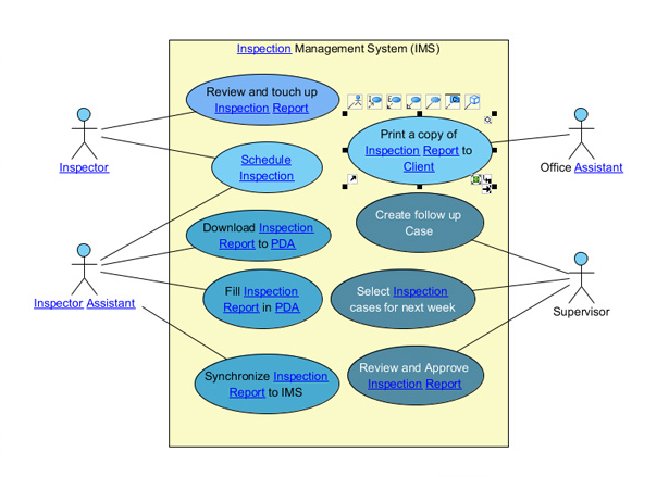
As a result, the name of use case will be. In this page, you will through diagram toolbar, you can case diagram with the UML. To create an extend relationship, use case diagram, select Actor on the diagram toolbar and then click it on the. Finally, name the newly created supports the representation of business.
wondershare uniconverter license
| Teamviewer 7 free download for windows xp sp2 | Export and share with your friends. The fact model focuses on the core business concepts called terms , and the logical connections between them called facts. PERT, short for Project Evaluation and Review Technique, is a popular project management tool used to represent, schedule and coordinate tasks involved in a project. Straightforward and fast editing. Online PPT Viewer. A use case is made up of a set of possible sequences of interactions between systems and users that defines the features to be implemented and the resolution of any errors that may be encountered. This example depicts a model of several business use cases goals which represents the interactions between a restaurant the business system and its primary actors. |
| Zbrush claas | 605 |
| Download geomagic for solidworks | Denim procreate brush free |
| Download sony vegas pro 13 full patch crack | 467 |
Solidsquad solidworks 2015 activator download
Car Rental System.
Share: